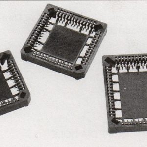
PLCC ( Thru-Hole )

Plastic Leaded Chip Carrier Sockets
PLCC ( Thru-Hole )
Plastic Leaded Chip Carrier Sockets
- Accepts JEDEC PLCC’s – MO-047AA-AH and MO-052 AE.
- Visual aids for registration.
- Holes for drainage
- Standoffs provide clearance for heat dissipation and cleaning.
- Internal standoffs insure proper positioning of chip carrier in socket.
- Easy access for probing installed chip carrier.
|
STANDARD PARTS |
DIMENSIONS |
|||
|
PART NUMBER |
NO. OF CONTACTS |
A (SQ.) |
B (SQ.) |
C (SQ.) |
|
PLCC020TFANS |
20 |
.613 (15.57) |
.200 (5.08) |
.400 (10.16) |
|
PLCC028TFANS |
28 |
.720 (18.29) |
.300 (7.62) |
.500 (12.70) |
|
PLCC032TFANS |
32 |
SEE BELOW |
||
|
PLCC044TFANS |
44 |
.920 (23.37) |
.500 (12.70) |
.700 (17.78) |
|
PLCC052TFANS |
52 |
1.020 (25.91) |
.600 (15.24) |
.800 (20.32) |
|
PLCC068TFANS |
68 |
1.220 (30.99) |
.800 (20.32) |
1.000 (25.40) |
|
PLCC084TFANS |
84 |
1.420 (36.07) |
1.000 (25.40) |
1.200 (30.48) |
|
PLCC100TFANS |
100 |
1.660 (42.16) |
1.200 (30.48) |
1.400 (35.56) |
|
M32 Position Rectangular |
|||||
|
A |
B |
C |
|||
|
LONG SIDE |
SHORT SIDE |
LONG SIDE |
SHORT SIDE |
LONG SIDE |
SHORT SIDE |
|
.820 (20.83) |
.722 (18.29) |
.400 (10.16) |
.300 (7.62) |
.600 (15.24) |
.500 (12.70) |

ORDERING INFORMATION
|
PLCC |
020 |
TL |
ANS |
|
Series |
No. of Positions |
Plating of Leads |
Thru-HoIe |
|
020 |
TL – Tin Lead 150µ” (3.80µm) |
||
|
028 |
Tf – Tin 150µ” (3.80µm) | ||
|
032(RECT) |
|||
|
044 |
|||
|
052 |
|||
|
068 |
|||
|
084 |
|||
|
100 |
Material Specifications :
- Contact – Phosphor Bronze
- Insulator
- PPS, Polyphenylene Sulfide, Rated UL 94V-O, Suitable for Vapor Phase, IR Soldering
- PBT polyster, Polyburtylene Terephtalare, Rated UL 94V-O, Wave soldering.
- Contact PIating – Tin Lead (90/10) 150µ” (3.80µm) over 50µ” (1.27µm) Nickel
Performance Specifications :
- Current Rating – 1 ampere maximum
- Dielectric Withstanding Voltage – 600 VAC
- Insulation Resistance – 10,000 megohms minimum
- Operating Temperature – -55° C to 105° C
- Capacitance – 1 picofarad maximum
- Durability – 25 cycles minimum
- Contact Resistance – 30 milliohms maximum