USO / SO
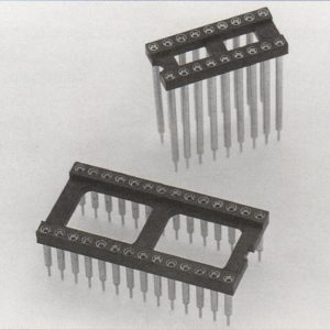
USO

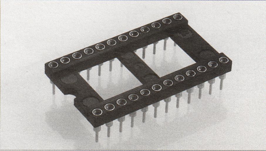
Open Frame Dip Socket
- Open insulator with ladder construction.
- Sockets are XY stackable.
- Machined outer sleeve with BeCu inner contact.
- Socket pins feature closed-end construction eliminating any solder wicking problems.
- Socket pins available in a wide variety of styles and plating options.
- Packaged in tubes compatible with automatic insertion equipment.
- Available with lubricated contacts for telecom applications.
|
Standard Parts |
DIMENSIONS (See Fig. 1) |
||||
|
PART NUMBER |
NUMBER OF PINS |
A |
B |
C |
D |
|
US0306XXXXX |
6 |
.300 (7.62) |
.400 (10.16) |
.300 (7.62) |
.093 (2.36) |
|
US0308XXXXX |
8 |
.400 (10.16) |
.400 (10.16) |
.300 (7.62) |
.093 (2.36) |
|
US0314XXXXX |
14 |
.700 (17.78) |
.400 (10.16) |
.300 (7.62) |
.093 (2.36) |
|
US0316XXXXX |
16 |
.800 (20.32) |
.400 (10.16) |
.300 (7.62) |
.093 (2.36) |
|
US0318XXXXX |
18 |
.900 (22.86) |
.400 (10.16) |
.300 (7.62) |
.093 (2.36) |
|
US0320XXXXX |
20 |
1.000 (25.40) |
.400 (10.16) |
.300 (7.62) |
.093 (2.36) |
|
US0422XXXXX |
22 |
1.100 (27.94) |
.500 (12.70) |
.400 (10.16) |
.093 (2.36) |
|
US0324XXXXX |
24 |
1.200 (30.48) |
.400 (10.16) |
.300 (7.62) |
.093 (2.36) |
|
US0624XXXXX |
24 |
1.200 (30.48) |
.700 (17.78) |
.600 (15.24) |
.093 (2.36) |
|
US0328XXXXX |
28 |
1.400 (35.56) |
.400 (10.16) |
.300 (7.62) |
.125 (3.18) |
|
US0628XXXXX |
28 |
1.400 (35.56) |
.700 (17.78) |
.600 (15.24) |
.093 (2.36) |
|
US0632XXXXX |
32 |
1.600 (40.64) |
.700 (17.78) |
.600 (15.24) |
.125 (3.18) |
|
US0640XXXXX |
40 |
2.000 (50.80) |
.700 (17.78) |
.600 (15.24) |
.093 (2.36) |
|
US0648XXXXX |
48 |
2.400 (60.96) |
.700 (17.78) |
.600 (15.24) |
.093 (2.36) |
|
US0964XXXXX |
64 |
3.200 (81.28) |
1.000 (25.40) |
.900 (22.86) |
.093 (2.36) |
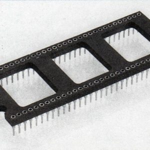
SO
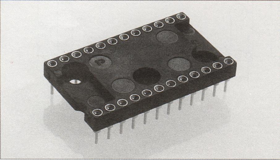
Closed Frame Dip Socket
- Closed insulator.
- Sockets are XY stackable.
- Machined outer sleeve with BeCu inner contact.
- Socket pins feature closed-end construction eliminating any solder wicking problems.
- Socket pins available in a wide variety of styles and plating options.
- Packaged in tubes compatible with automatic insertion equipment.
- Available with lubricated contacts for telecom applications.
|
Standard Parts |
DIMENSIONS (See Fig. 1) |
||||
|
PART NUMBER |
NUMBER OF PINS |
A |
B |
C |
D |
|
S0308XXXXX |
8 |
.400 (10.16) |
.400 (10.16) |
.300 (7.62) |
.093 (2.36) |
|
S0314XXXXX |
14 |
.700 (17.78) |
.400 (10.16) |
.300 (7.62) |
.093 (2.36) |
|
S0316XXXXX |
16 |
.800 (20.32) |
.400 (10.16) |
.300 (7.62) |
.093 (2.36) |
|
S0318XXXXX |
18 |
.900 (22.86) |
.400 (10.16) |
.300 (7.62) |
.093 (2.36) |
|
S0320XXXXX |
20 |
1.000 (25.40) |
.400 (10.16) |
.300 (7.62) |
.093 (2.36) |
|
S0422XXXXX |
22 |
1.100 (27.94) |
.500 (12.70) |
.400 (10.16) |
.093 (2.36) |
|
S0624XXXXX |
24 |
1.200 (30.48) |
.700 (17.78) |
.600 (15.24) |
.093 (2.36) |
|
S0628XXXXX |
28 |
1.400 (35.56) |
.700 (17.78) |
.600 (15.24) |
.093 (2.36) |
|
S0632XXXXX |
32 |
1.600 (40.64) |
.700 (17.78) |
.600 (15.24) |
.125 (3.18) |
|
S0640XXXXX |
40 |
2.000 (50.80) |
.700 (17.78) |
.600 (15.24) |
.093 (2.36) |
FIG 1 FIG 2
FIG 2 
ORDERING INFORMATION
|
SO |
3 |
18 |
TL |
A |
31 |
|
Series |
DIP Spacing |
Pin Number |
Plating 0f Sleeve |
Loose Pin Number |
Plating of Inner Contact |
|
USO (Open) |
3 – .300 (7.62) centers |
TL – Tin Lead 200µ” (5.08µm) |
Solder Tail Length |
30 – GoId 10µ” (0.25µm) |
|
|
SO (Closed) |
4 – .400 (10.16) centers |
TB – Tin Lead 150µ” (3.80µm) |
See Fig 2 |
31 – GoId 30µ” (0.75µm) |
|
|
6 – .600 (15.24) centers |
GH – GoId lOµ” (0.25µm) |
(E Dim.) |
45 – GoId 15µ” (0.38µm) |
||
|
9 – .900 (22.86) centers |
GK – GoId 30µ” (0.75µm) |
A – .125(3.18) . . . .3000 |
36 – Tin Lead 200µ” (5.08µm) |
||
| Tf – Tin 200µ” (5.08µm) |
B – .143(3.63) .. . . .3080 |
27 – GoId 5µ” (0.l3µm) |
|||
|
C – .180(4.57) . . . .3010 |
36F – Tin Lead 200µ” (5.08µm) with lubricant |
||||
|
D – .275(6.99) . . . . 3190 |
34 – Tin 200µ” (5.08µm) | ||||
| 34F – Tin 200µ” (5.08µm) with lubricant |
Specifications:
- Inner Contact – BeCu per QQ-C-533.
- Outer Sleeve – Brass per QQ-B-626.
- Insulator – Glass-filled Polyester Rated to UL94V-O.
- Operathg Temperature – -650C to +1250C.
- PCB Hole Size – .035 +- .003 (0.89 +- 0.08) solder termination.
- Ail Platings – Over 100 µ” (2.54 µm) minimum Nickel over 5 µ” (013 µm) minimum Copper.
- IC Pin Dimension Range – .016 (0.41) to .025 (0.63) round, .125 (318) minimum length,
- .009 (0.23) x .015 (0.38) to .015 (0.38) x .022 (0.56) rectangular.
- Insertion Force – 186 grams.
- Withdrawal Force – 92 grams.

